Bill Kotaska's Busicom 141-PF replica
Quick links:
Narrative
I had to overcome several challenges to build a replica of this 37 year old calculator. My goal while designing the replica was to enable the software from the original Busicom ROMs to run unaltered and provide an input/output experience as faithful to the original as possible.
I used many of the techniques in the Busicom 141-PF replica in an earlier project of mine, a single board 4004 "trainer". In that project, I gained experience with the MCS4 family and how to interface these chips with standard TTL devices. This served me well in keeping the parts count low.
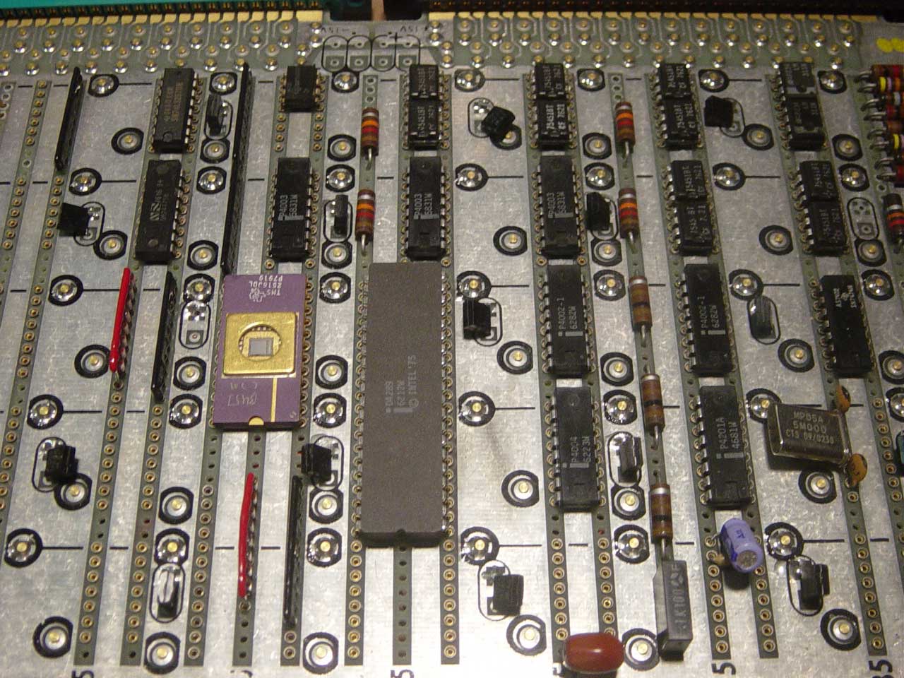
The original 4001 ROMs used in the Busicom were designed to work with the 4004's unique bus structure. Since these were mask programmed, no direct replacement was possible. As part of the evolution of the 4004/4040 family, Intel's developed the 4008 and 4009 "Standard Memory Interface" chips, and later combined them into a single chip, the 4289, to allow these early microprocessors to interface to standard ROMs. I had used the 4289 chip my single board 4004 trainer, so I was already familiar with it. Ironically the 40-pin 4289 is huge compared to the 16-pin 4004.
The two-phase clock in the original calculator was generated using a discrete transistor oscillator. Later Intel introduced the 4201 single chip clock generator, which I used to generate the clock in the replica.
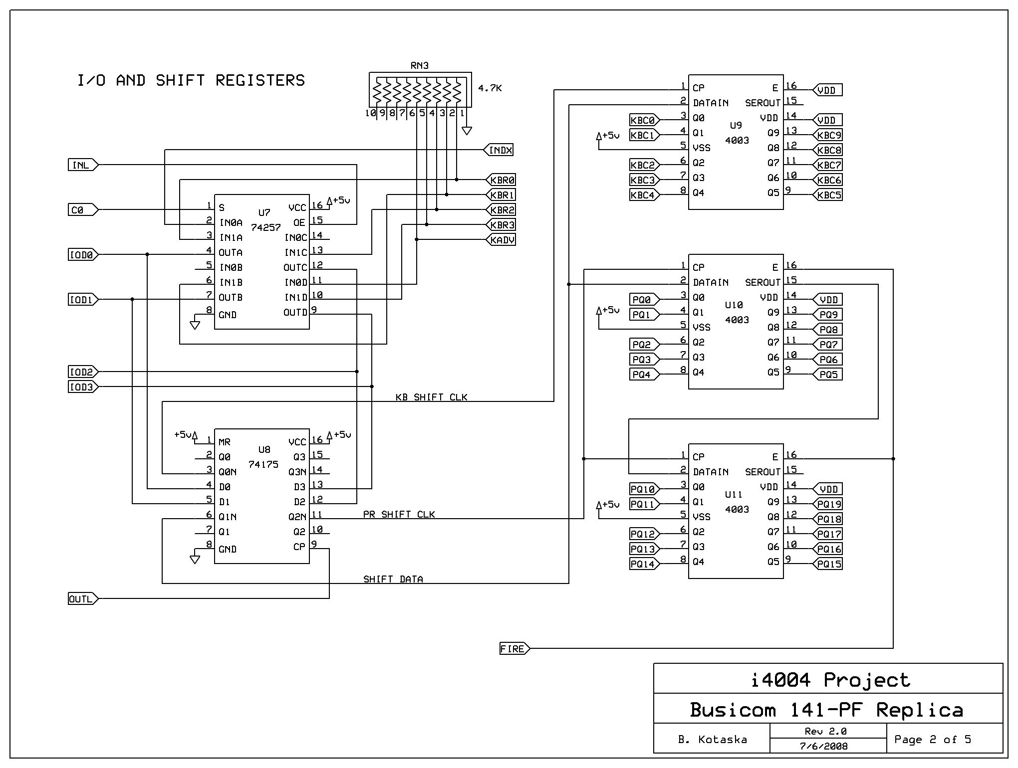
I had already collected a 4004 chipset. The only original chips I was missing for the calculator replica were the 4003 shift registers. These are simple enough in function that I decided to use a PIC 18F1320 microcontroller to emulate them. My first version of the replica was functioning with three PICs in place of the 4003's. Tim McNerney graciously donated three real 4003's and I was able to easily modify my replica to use them instead of the PICs.
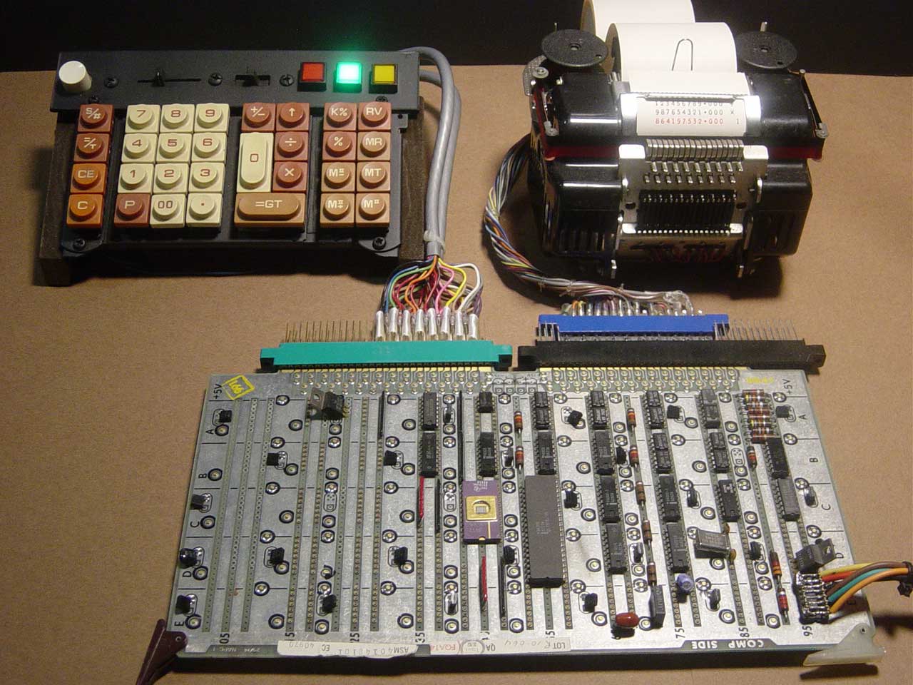
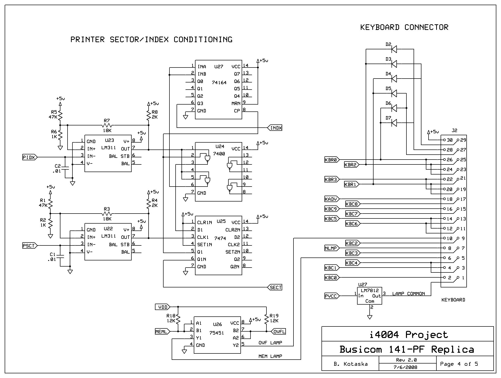
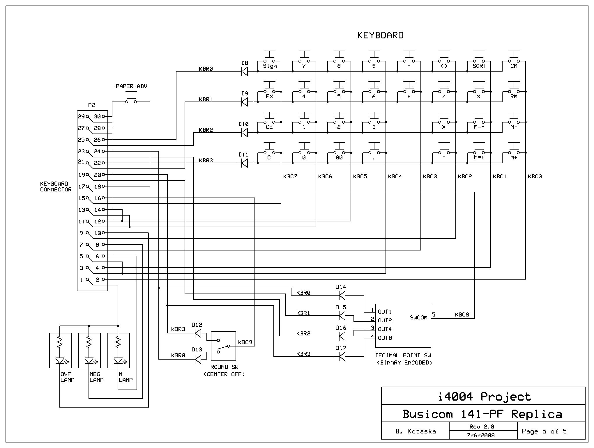
The keyboard in the original calculator was made using a discrete matrix of reed switches. I thought it would be nice if the keys had a look of authenticity about them. Browsing eBay, I found a calculator with a similar style of keycaps. Given the age of the calculator, the switches were most likely the mechanical contact type that I needed. After receiving this calculator, I went about disassembling the keyboard. The keyswitches were mounted on a metal frame. By cutting this frame into sections and rearranging, I was able to match the original Busicom layout.
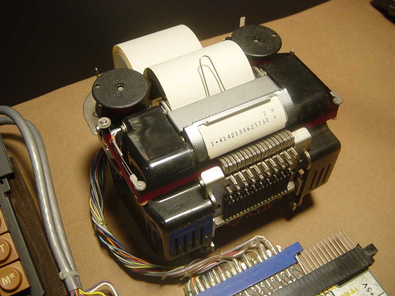
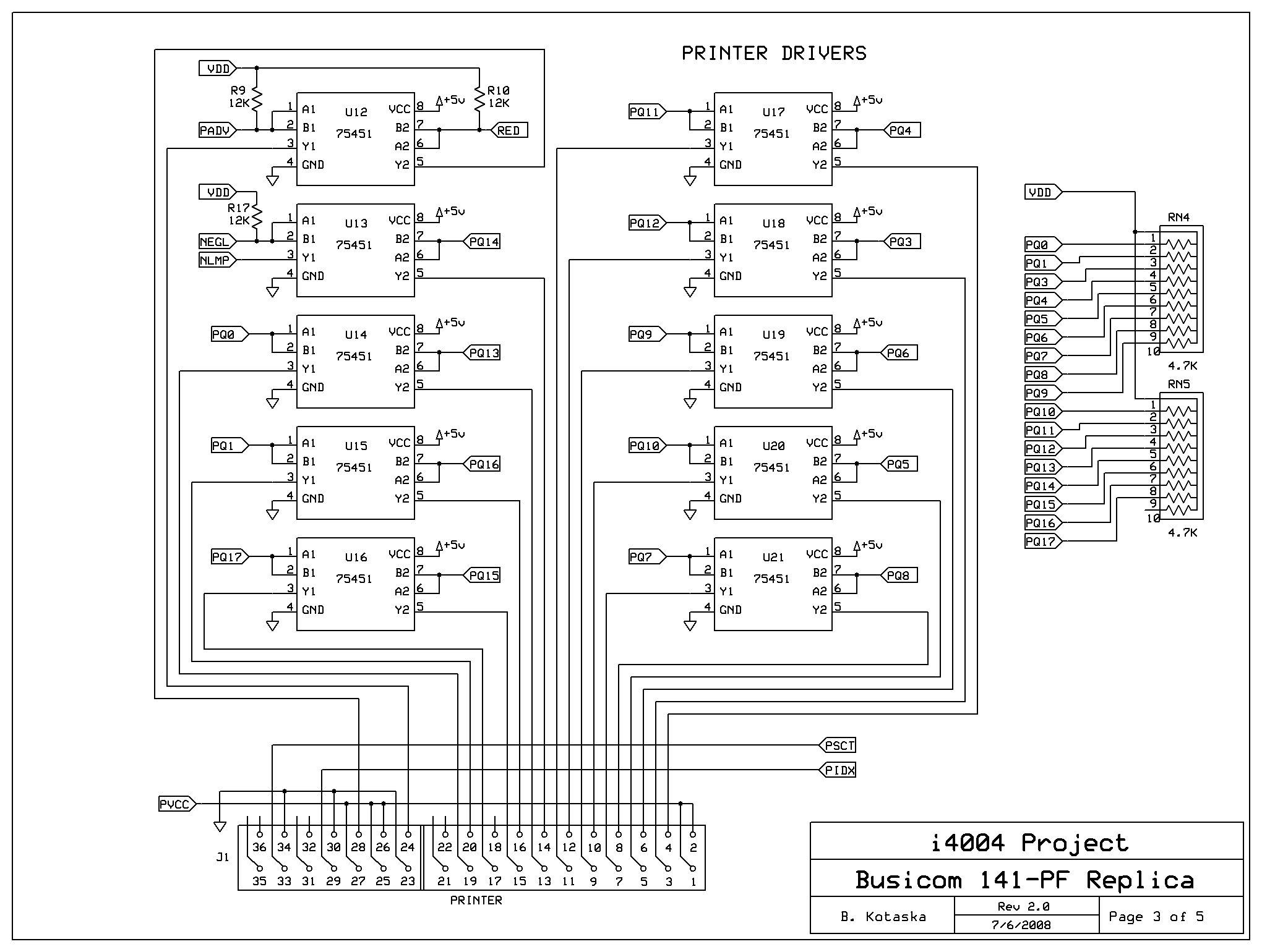
The printer used in the original calculator was a second generation flying drum "line printer" made by Shinshu Seiki, better known as Epson. The Model-101 printer was developed specifically for use in official timekeeping equipment at the 1964 Tokyo Summer Olympics. The Model-102 printer I salvaged from an old Monroe 1330 calculator. It is electrically and mechanically indentical to the original printer that Busicom used, except for the drum's custom character-set is different, most notably the special symbols in the right two columns. To make numbers print correctly without modifying Busicom's software, I added a hardware shift register to delay the printer's index pulse (aka "vertical sync") to compensate for the digits being offset by three sectors.
I had some question early in the design about how the printer's analog sync pulses were converted to clean digital signals the original calculator. A full schematic does not exist. By studying the Busicom "source code" originally reverse-engineered by Brian and Barry Silverman and extensively analyzed and commented by Lajos Kintli, I was able to determined that some of the discrete components in the original calculator were being used to condition the printer signals. The printer signals are conditioned in my replica using comparators and TTL logic.
The replica is constructed using wire-wrap techniques on an old Garry wire-wrap prototyping board. This robust, solder-free approach made it easy to change the circuit as needed, and offers an attractive "vintage look" perfect for reproducing a 1970's era legacy project.
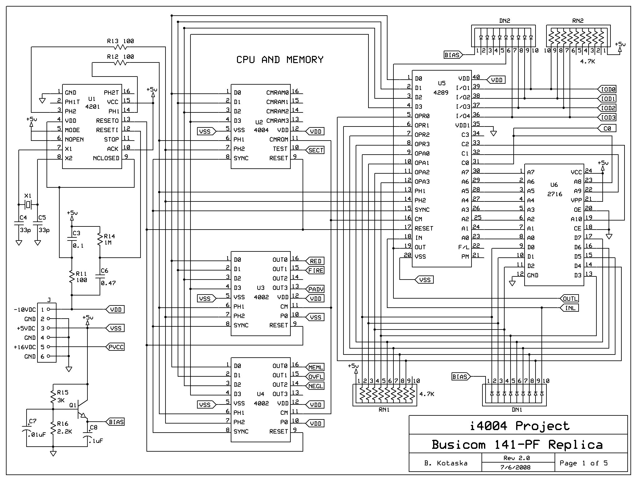
Busicom 141-PF Replica Schematics
New - Version 2 (Updated 11/18/2008) — Click on each thumbnail to view full-size image.
Tim McNerney's Shinshu Seiki Model-102 printer emulator for PIC18F2320
This hardware emulator converts the printer interface signals that come from the calculator hardware into ASCII characters output over the PIC's serial port (configured by default to drive an external RS-232 level shifter). This interface can be used to drive a serial LCD display, PC running a terminal emulator, etc. The emulator also provides the calculator firmware running on the 4004 with the all-important "heartbeat" sync pulses. Without the proper timing pulses, the calculator won't work at all!
I built the exerciser to test the emulator. This was necessary because my own hardware replica wasn't quite working yet (and then Bill "scooped me" :-). The exerciser runs on a separate PIC connectected to the emulator PIC. It generates all the signals that the calculator would send to the printer, and responds to the index pulses. I extracted the test data by running calculator examples on an instrumented 4004/Busicom simulator written in Java.
I used the CCS C compiler to deploy the emulator on the PIC. In test mode, the code probably still compiles with gcc and runs under POSIX with little or no modifications.
Legal Notices
- The software (e.g. simulators) and engineering documents (e.g. schematics) are provided "AS IS" with no warranty expressed or implied. Fitness for any particular purpose is not guaranteed. The authors do not accept any liability for use of this information.
- The works on this web site are licensed under a Creative Commons Attribution-Noncommercial-Share Alike 2.5 License.